Thermolyne Furnace Repair
- Joseph Boettcher
- Nov 30, 2023
- 4 min read

Updated: Dec 1, 2023
My collogue and friend was working at a local foundry last year and they were planning on throwing away a larger lab scale Thermolyne muffle furnace that is capable of reaching 2450F. I thought that it wasn't in too bad of shape and they agreed to give it to me for free but I had to get it gone. I paid to have it shipped it LTL from Saint Louis to Kansas City.
Upon receiving it I found that one of the elements had burnt out and there was a mostly melted bar of unknown ferrous material in the hearth. The hearth was also wrecked. I attempted to tig weld the element and that went about as expected. The only solution at this point was to make an new element. It's pretty fortunate that only one element sas burned out.


On the path of starting making a new element I needed to figure out the following:
The material
Wire gauge
Element total length
Element ID and OD
Pitch of twist
Element terminal material
The first order of business was determine the material and wire gauge. I measured the wire and it was ~0.100" so it was 10 gauge wire. I determined measured the ID, OD and the pitch by measuring the length of one side of the coil and dividing it by the number of revolutions. The pitch was 10 revolutions per inch. I determined that the total coil length was 100 feet.
I knew that it was a high temperature resistive heating wire and probably some kind of kanthal. I determined the restivity of the wire by measuring the resistance of half of the broken element and multiplying the resistance by the cross sectional area divided by the length of wire measured (50 feet). I determined from the restivity that the material was Kanthal A-1.
Now it was time to make the element but how? The material was too strong to bend by hand and I wanted the pitch to be accurate as well, bending by hand was not possible. I had seen that people used lathes to turn springs before.
I thought of a setup that would work. I bought a 3' 4140 rod that was the same ID as the coil ID. I drilled a center hole for a live center in one end. I took advice from a toolmaker coworker/friend and used peices of 1/2" keystock to make a guide that would fit in the tool post. For the guide I clamped the two peices keystock in the mill vise and drilled a 1/8" hole at the seem of the two peices of keystock with a drill bit. I followed it up with a center drill countersink to guide the wire.
I set the lathe to the lowest rpm possible and to set to thread in reverse at 10 threads per inch. Placed the 4140 rod in the chuck and the live center in the center hole. I used 3' peices of 1/8" aluminum tig filler rod for practice runs. I clamped the wire to the rod near the chuck and ran the wire through the tool post guide. Starting the lathe up for the first time was a stressful experience as I was worried I would bend my expensive 4140 bar into a pretzel or something worse happen that I didn't have the forethought to foresee. The first test went well though. The only thing that needed fixed was that I needed a follower rest. For the follower rest I used another peice of keystock in the tool post with a half circle milled in it. You can see towards the end of my first video it almost wound itself into a pretzel towards the end.
I did another test run with the follower rest and it worked great! Making the element went great and I am glad I practiced before with aluminum. The winding worked the very first time and I didn't even have any scrap. I left a small gap of about 1.5" between the two windings.
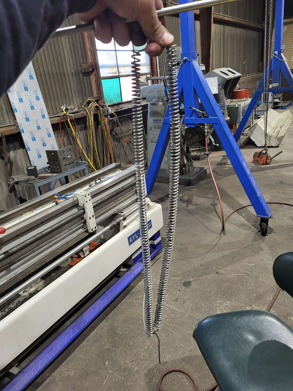
I used an acetylene torch to stretch the wire to the perfect length and bend the right shape into the front of the element.
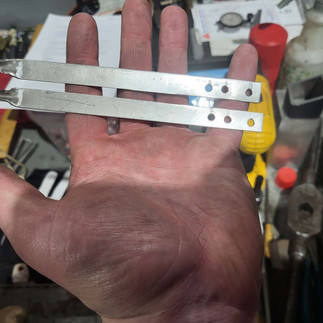
Now for the terminals. I used 310 stainless because of its exelecent high temperature corrosion resistance, even better and cheaper than some inconels. I cut the strips out of 310 with a cut off wheel to match the terminal ends caps. Drilled holes and bent the ends. The element was now ready for final welding.


I used a 308 stainless filler and tig welded the coil into the terminals. It came out really good I thought.


Next step was to install it into the the furnace. When I went to install it I noticed there was no insulation left in any of the terminal holes so I packed all 32 or more with keowool. I think this will help with heat leaking out the back of the furnace.


After I reinstalled the wires we tested the furnace, we took it up to 600F and checked it with the flir infrared camera. It worked great.
I now have it at home but there is two things keeping me from using it at home.
It is wired for three phase 220v, pulling 34 amps. This would require me to have a 70A single phase circuit in my garage (the furnace outputs 12.2kw). Which would require a ~20hp solid state phase converter.
There is no overtemp protection in case the thermocouple fails, which would cause the furnace to get much too hot or meltdown. This wouldn't be too much of an issue in a more industrial setting but at home it would be something I need.
I also am currently fabricating a work bench for the furnace. I'll do another blog post on that. I look forward to getting a more industrial shop space in the future and using it there for heat treating steel and possibly melting nonferrous metals for castings.
Comments